NMR500 Basic
Operation
Basic Steps
Note:
- Only authorized users can tune the probe or conduct VT experiments on NMR500.
- For quick shimming and good linewidth
and shape, keep sample volume as close as possible to 700uL.
- Login with username and password
- Enter a valid group project code
- Open vnmrJ
- Check temperature before inserting sample. Check VT display and check
with temp command. Normal setting is OFF.
- For variable temperature operation, read the VT
operation procedure.
- Eject current sample and load new sample (Keep sample straight up during
sample change. Use care not to break tube!!)
- Check spinning setting. Spinning is default at 20Hz. If spinning is not
on, set rate to 20 and click
Start→Standard→Spin.
- Load standard shim values and 1H parameters: type
init1h (or initshims for shims
only).
- Load desired experiment parameters if needed. Type su
- Change solvent and type su
- Tune probe for all channels to be used if necessary and permitted.
- Make sure correct ¼-wavelength cable is installed on broadband preamp for
the nucleus detected (For broadband direct detection only)
- Lock
- To use autolock, click
Start→Standard→Find Z0
- For manual locking, turn lock off and change Z0.
Once step-function is loocated, turn lock ON.
- Shimming:
- To use autoshimming, click
Start→Standard→Gradient shim
- For manual shimming, starting lock at ~70%,
adjust Z1 and Z2 for maximum lock signal.
- Readjust lock power and gain to set lock level ~70-80% after
shimming.
- Collect data. Change parameters (sw, nt, ...) Type go (or
ga, or click
Acquire button)
- Process data: wft
- Type aa or click
Stop/Abort button to stop data
acquisition if needed
- Phase (aph), correct
baseline (dc or bc), integrate, pick peaks,
and print. Use data station for detailed processing.
- Save data (File->Save or type svf).
- Eject sample and insert Idle sample.
- If X-channel is tuned to other nucleus other than C13, tune it back to
C13 for X. Put back C13 ¼-wavelength filter.
- Sign off and note issues.
When NOT to spin
- Spinning should be turned OFF
for all 2D experiments, any experiment that does editing from scan to scan
(such as CYCLENOE and DEPT) and any
experiment with gradients.
- In certain experiments that require high spectrometer stability (rather
than slightly sharper peaks), such as in T1 and T2 measurements, and
experiments where peak height or integration is tracked over time, or where
spinning sidebands interfere with analysis, spinning should be turned
off.
- When spinning is turned off, adjust X1 and Y1 shims, and then Z1 and Z2
shims.
For best lock stability:
- For best locking and stability, lock level should be set to 70%-80% level
for most experiments, particularly the ones with gradient pulses and long
overnight experiments.
- Ideally, lock power should be set high but just below the lock saturation
point (~ 3dB below saturation power). Then, adjust gain to bring lock to
70-80% level. A saturated lock tends to fluctuate up and down and makes no
further gain in lock level if power is increased.
- To check whether lock is saturated:
- Drop lock power by 6 unit (dB). If the lock
level drops ~ 50%, lock is not saturated. If the lock level drop is a lot
less than 50%, it is saturated.
- The saturation power depends on solvent. On the
same spectrometer, with the same probe and solvent, the saturation power
should be consistent over time.
Background
Channels and Nuclei
An indirect detection probe (IDP) is designed for optimal H1 direct
detection and indirect detection (through transient 2nd or
3rd dimension) of other nuclei. A broadband probe (such as the
switchable probe or SWP on NMR500) is optimized for broadband nucleus direct
detection while decoupling H1 or F19. A broadband nucleus is any nucleus other
than H1 and F19 carrying lower Larmor frequency.
Each probe is designed with a fixed number of channel inputs for nuclei in
different frequency range. On a broadband probe, such as SWP, there are
typically three channel inputs: 1H, X nucleus, and the lock (2H). The X channel
can be set to any broadband nucleus with a change of a tuning stick (no stick
is needed for C13).
The name "channel" is a confusing name that is still being widely used. Do
not confuse the “channel” (input ports) on the probe with the
channel names in the console and the channels in vnmrJ. The three "channel" names are completely separate
in principle. In the console, a channel refers to an amplifier output. In vnmrJ, the channel name is a more abstract, but each
channel is usually tied with an amplifier output in the console and carrying a
frequency bandwidth. The channel mapping and signal routing are mostly
automatic, but can also be manipulated by users. On NMR500, channels 1 and 2 in
the console are full-band (covering both high 1H/19F and low frequencies for X
nuclei), equivalent and can be set to any nucleus. In most experiments on
NMR400 and 500, only channel 1 and sometimes channels 1 and 2 are used. Channel
1 in vnmrJ is usually also the direct detection channel.
Direct Detection and Decoupling
In vnmrJ, channel 1 is used for direct
detection. Channels 2, 3 ... are called decouplers
(decoupler 1, decoupler
2 ...) for historical reasons. For example, C13 direct detection involves
setting channel 1 to C13 and channel 2 to H1 (decoupling). Each channel has its
own default parameter names for hardware and data collection parameters. The
most important parameters you may encounter are:
- Channel 1 (direct detection)
- sfrq (transmitter frequency)
- tof
(transmitter offset, center of spectrum, in Hz)
- tn (nucleus, i.e. H1, C13, P31
....)
- tpwr (RF pulse power level,
dB)
- pw (pulse width, usec)
- sw(spectral width)
- Channels 2 and 3 (decoupling or indirect detection)
- dfrq,
dfrq2 (decoupler
frequency)
- dof,
dof2 (decoupler offset, center of
spectrum)
- dn,
dn2 (decoupler
nucleus)
- dm, dm2 (decoupling status
flag)
- dmm,
dmm2 (decoupling scheme)
- dpwr2, dpwr3 (decoupling
power)
- dseq,
dseq2 (decoupling sequence)
- dmf,dmf2 (decoupling modulation
frequency)
Probe Tuning
NOTE: New arrangement requires all users not to tune the probe
unless permitted by the Manager. The instrument should be left tuned for H1 and
C13 detection with a default CDCL3 solvent.
Brief Tuning Steps
NOTE: Before tuning, make sure to have the right nucleus setting for the
channel used (type tn? for channel 1, dn? for
channel 2 to check.). Type su before tuning.
**For 1H or 19F tuning
For F19, make sure to replace the filter on the right side of preamp to a
F19 filter.
- Disconnect the cable from the probe side of the 1H filter and connect it
to the PROBE port of the tuning interface.
- Disconnect the cable from the OUTPUT port on the 1H/19F preamp and
connect it to the OUTPUT port on the tuning interface.
- Press the channel button to the desired channel with the desired nucleus
setting (typically either 1 or 2).
- Press attenuation button (typically to 9) to see a number in tuning
display. Set attenuation to 9 (minimum attenuation) before finishing
tuning.
- Turn the 1H tuning control (iterative between top and bottom portions) to
minimize tuning reading, ideally to below 10.
- Once tuning is finished, press the channel button to set it to 0 (zero).
- Disconnect the cable from the PROBE port on the tuning interface and
connect it back to the probe side of the 1H filter.
- Disconnect the cable from the OUTPUT port of the tuning interface and
connect it back to the OUTPUT port of the 1H/19F Preamp.
**For broadband nucleus (C13, P31, Li7, N15 ... etc) tuning.
- Check nucleus setting and frequency, and type su
- Insert the correct tuning stick into probe. Do not over-tighten
it. As soon as it hits resistance, stop turning it.
- Turn tuning control (top control) to roughly match value displayed on a
label on the side of the probe for the intended nucleus (or to the value
for the closest nucleus in frequency)
- Disconnect X-channel cable from the filter end and connect it to the
PROBE port on of the tuning interface. Disconnect the cable from the OUTPUT
port on the broadband preamp and connect it to the OUTPUT port on the
tuning interface.
- Press the channel button to correct channel number
- Press attenuator button (9 or lower) to display a number. Tune with
attenuator set to 9 before finishing tuning.
- Turn the X-channel matching control (bottom control) to minimize tuning
reading, ideally to below 10. Adjust top control (tune) slightly and the
bottom match control iteratively to minimize reading.
- Once finished, press the channel button to have it set to 0 (zero).
- Disconnect the cable from the PROBE port on the tuning interface and
connect it to the probe side of the broadband filter.
- Disconnect the cable from the OUTPUT port of the tuning interface and
connect it to the OUTPUT port of the broadband preamp.
- Install a ¼-wavelength cable matching the detection frequency if direct
detection of X nucleus is intended.
Detailed Tuning Steps for H1 and F19
This instruction is for the SWP probe on NMR500, but it generally applies to
other probes on NMR500 with minor changes.
First, load the experiment to be performed and make sure the channels to be
tuned have the right nucleus setting. To find out this info, type tn?
(for channel 1), or dn? (for channel 2).
If it is not the intended nucleus, for tuning purpose you
can simply enter at the command line under any experiment, for example,
tn='C13' or dn='H1' and then tune channel 1
for 13C and channel 2 for H1. Type su before tuning.
**For H1 Tuning
No tuning stick is needed for 1H tuning.
- Disconnect the cable from the probe side of the
1H filter (long cylinder on the right side of the
1H/19F preamp). Connect this cable to the PROBE port
on the tuning interface. Disconnect the cable from the OUTPUT port on the
1H/19F preamp and connect it to the OUTPUT port on the tuning
interface.
- Press the
channel "+" button at the top of the tuning interface to the corresponding
channel number (typically to either 1 or 2). A green light with a tune
number will come on.
- Make sure
the attenuation, next to the channel setting, is displayed at 9 (minimum
attention). If the tuning display number is shown as –E with the
attenuation set to 9, it means the tuning is way off (with a tune number
over 999) and the tuning signal needs to be attenuated (only temporally).
Press the "-" button to reduce it to 8, 7 .,..
until you see a number displayed.
- Locate
the labeled H1 tuning control stick on the bottom of the probe. With one hand holding the tuning control and your eyes
reading the tuning display number, turn the bottom match control to
minimize reading. Once a minimum reading is reached, turn the top tune
control until a new minimum is reached. Then, turn the bottom match control
again, and then the top tune control, back and forth until the reading
cannot be made any smaller. A reading <10 for 1H is mostly sufficient.
- If the reading is still high after this iterative
process (over 10), over-shoot (turn the top control in one direction) to
make the reading bigger by ~ 100-200, and then turn the bottom control to
reach minimum reading. If the number is smaller than the starting value,
turn the top control in the same direction as you just did to make the
reading bigger, and then turn the bottom control to make the reading
smaller, until you reach the best, lowest reading you can get. If the
reading does not improve or becomes worse by over-shooting the top control
in one direction, turn the top control to over-shoot in the opposite
direction. Remember we are searching in a two-dimensional (tune and match)
space for a global minimum. Over-shooting one of the controls (make the
reading temporarily bigger) let you overcome local minimum trap and find
the global minimum.
- Once
tuning is finished, press the channel "-" to have it set to 0 (zero). The
display light turns off.
- Disconnect
the cable from the PROBE port on the tuning interface and connect it back
to the probe side of the 1H filter.
- Disconnect the cable from the OUTPUT port of the
tuning interface and connect it back to the OUTPUT port of the 1H/19F
Preamp
**For F19 tuning
- Same as
1H tuning
- Make sure
the H1 filter is replaced with the F19 filter
Detailed Steps to Tune for X-nucleus (C13, P31, .. etc)
The procedure is similar to H1 channel tuning. Read H1 tuning procedure
above for additional details. The tuning procedure for any broadband nucleus is
identical, except:
- For C13, no tuning stick is needed in the SWP probe. Remove any stick
left in the stick slot. Remember this requirement is a probe-specific
feature.
- A different tuning stick might have to be used for any nucleus other than
C13, depending on the nucleus frequency.
- Cables are disconnected/connected from the broadband preamp (left) for
tuning
- Make sure a proper ¼-wavelength cable is installed on the broadband
preamp if direct detection is intended
STEPS:
- Check nucleus frequency and find the correct tuning stick in the probe
box.
- To check nucleus frequency, type tn? (or dn?
for the decoupling channel) to make sure the nucleus is correct. Type
sfrq? (or dfrq?
for the decoupling channel). Find a tuning stick with the frequency range
covering this nucleus frequency.
- Insert
the tuning stick into the empty slot at the bottom of the probe. Turn the
stick clockwise (looking from the bottom) while slightly push the stick up
to screw the tip into the slot. Do not over-tighten
it.
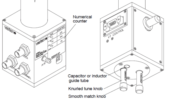
- On the side of the SWP probe bottom, a label displays rough tuning values
for some common nuclei. Turn the top tuning control for X nucleus until the
number in the small display window next to the label matches the one
designated for that nucleus. If your nucleus is not among those listed, try
one that is closest in frequency.
- Disconnect the cable from the probe side of the two small square filters
connected to the broadband preamp (left). Connect this cable to the PROBE
port on the tuning interface. Disconnect the cable from the OUTPUT port on
the broadband preamp and connect it to the OUTPUT port on the tuning
interface.
- Press the channel "+" button on the tuning interface to the corresponding
channel number (typically to either 1 for direct detection or 2 for
decoupling). A green light with a tune number will come on.
- Make sure
the attenuation, next to the channel setting, is displayed at 9 (minimum
attention). If the tuning display number is shown as –E with the
attenuation set to 9, it means the tuning is way off (with a tune number
over 999) and the tuning signal needs to attenuated (only temporarily).
Press the attenuation "-" button to reduce it to 8, 7
.... until you see a number
displayed.
- Locate
the labeled X nucleus tuning control on the bottom of the probe. With one hand holding the tuning control and your eyes
reading the tuning display number, turn the bottom match control to adjust
matching. Once a minimum reading is reached, turn the top tuning control to
adjust tuning (adjust frequency) until a new minimum is reached. Then, turn
the bootom match control again, and then the top tuning control, back and
forth until the reading cannot be made any smaller. A reading <10 for 1H
is mostly sufficient. Remember the tuning display on the side of the probe
should not deviate from the indicated vavlue by a few units.
- Once the tuning number comes down, press the attenuation button to 9 and
tune with this setting
- If the reading is still high after this
iterative process (over 10), over-shoot (turn the top control in one
direction) to make the reading bigger by ~ 100-200, and then turn the
bottom control to reach minimum reading. If the number is smaller than the
starting value, continue to turn the top control in the same direction and
then adjust the bottom control until you reach the best, lowest reading you
can get. If the reading does not improve by over-shooting the top control,
it means you need to turn the top control to over-shoot in the opposite
direction, and adjust the bottom control.
- Once tuning is finished, press the channel "-" button to have it set to 0
(zero). The display light turns off.
- Disconnect the cable from the PROBE port on the tuning interface and
connect it to the probe side of the broadband filters.
- Disconnect the cable from the OUTPUT port of the tuning interface and
connect it to the OUTPUT port of the broadband preamp.
- Install a ¼-wavelength cable matching or covering the detection frequency
if direct detection of X nucleus is intended
H. Zhou
updated Aug 2011