Qtune
H.Zhou updated
Feb 2011
Qtune is an alternative, graphic interface for probe tuning
in vnmr software. It's been available since the early versions of the
software. Due to the very different tuning sensitivity of the repaired SWP
probe, it becomes necessary sometimes to use qtune to quickly tune the probe.
The only issue is that good eyesight is needed to watch the displayed curve on
the monitor from a distance. We'll try to possibly add a second monitor closer
to the magnet legs just for this purpose. Before that, you may have to walk
back and forth a bit. It is helpful to turn the computer minotor towards you for
better viewing. The qtune procedure should work with other probes and on NMR400
as well.
Procedure
The cable connections are the same as in the normal tuning method using the
tuning interface in between the broadband and 1H/19F preamp boxes. The only
difference is that you do not change the tune channel and attenuator setting
from the interface (see below).
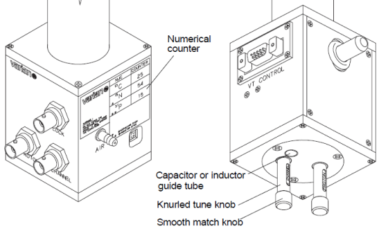
- Install, if necessary, a capacitor (or inductor) stick in the probe. Make sure the stick
is all the way in. You may have to overcome small resisitance as you screw
the stick in, but do not overtighten it. Turn the tune knob (top section of
X-channel tuning knob) so that the displayed value in a small window on the
side of the probe matches the labeled value.
- Install a 1/4-wavelength cable on the broadband preamp for the desired
nucleus
- Disconnect the X-channel cable from the filters on the broadband preamp
(left) and connect it to the PROBE port on the tuning interface.
- Disconnect the cable from the broadband preamp OUTPUT port and connect it
to the OUTPUT port on the tuning interface.
- Leave channel at 0 and attenuation at 9.
- In vnmrJ, type qtune.
- Select the desired nucleus from the
"Select Center Frequency" pulldown menu.
- Click "Start Probe Tune"
- Change Power to 20dB. Press
Enter key.
- Click "Autoscale". Unless the
probe is way out of tune, it should see a curve with a dip.
- If you do not see a dip, first try to increase
the frequency span. Enter a larger value (i.e. 20) in the
"Span" field and press Enter. Once tuning
is improved, you need to decrease this span back to ~ 10 MHz so that you
can center the dip better.
- The displayed tune number in the window in the
probe body should be within ~2-3 units of the designated value. If turning
the bottom match knob does not cause a response in the tuning curve, try to
turn the knob all the way from one end to the other end.
- Turn the match knob to bring down the dip, to touch the baseline if
possible.
- Turn the tune knob to center the dip at the vertical, center line.
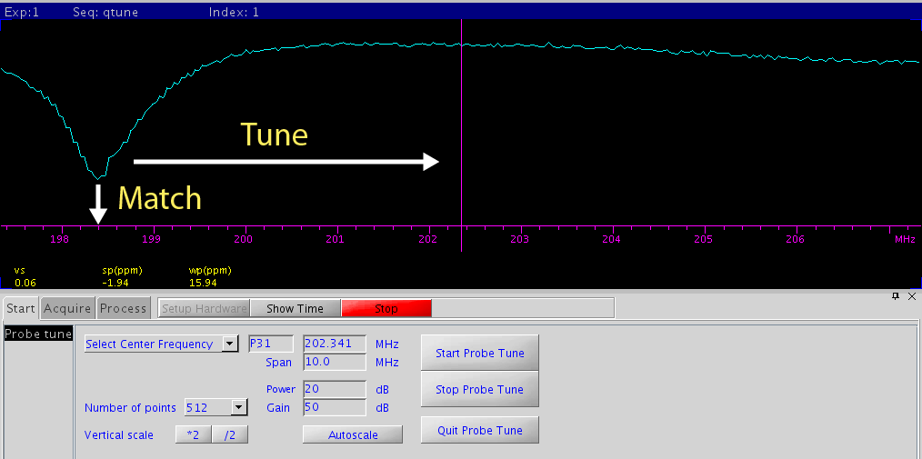
The following is what you see if the P31 channel is way-off tune and match.
Tuning the probe actually has two different aspects: tune and
match.
- Tune is to bring the response
frequency of the probe channel to the desired resonance frequency (dictated
by the detection nucleus).
- Match is to reduce the impedance
at a particular frequency.
- The end result needed is to center the
dip and make the dip as deep as possible.
Tune
and Match
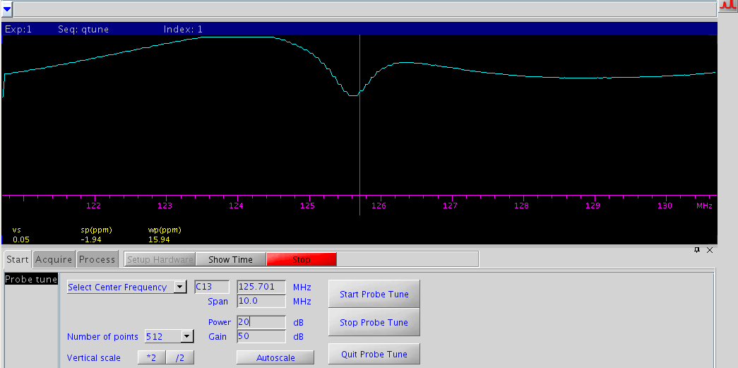
C13 as an example
Initial
look of C13 tuning graph. Match is way off. Tune isn't as bad.
|
|
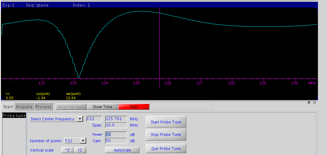
First,
turn the match knob (bottom section of the tune control) to bring down
the dip as deep as possible. This may temporarily shift the dip off center.
 |
|
Next,
turn the tune knob (top control) to bring the center of the dip to
match the center line (C13 frequency).
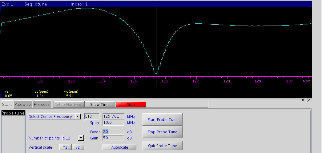 |
|
Next,
fine adjust tune/match knobs to have the dip centered and deep,ideally
touch the horizontal axis (this may not be possible for some nuclei).
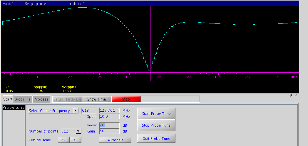 |
|
|
Click "Stop Probe Tune", then click "Quit Probe Tune". Probe tuning is complete. |
|
- After tuning, connect the X-channel cable back to the filter. Connect the
tune output port cable back to the OUTPUT port on X-channel preamp
- After you are done with the experiments, reverse the changes you have
made to the default for C13 detection
- Remove tuning stick from probe
- Change the 1/4-wavelength cable to that for
C13
- Tune probe back for C13 with a sample with CDCl3
as solvent.


